
Private previewCO2 geological storageRecorded evidence
Terra MultiphysicsProfileEarly access
Johansen-type formationReal solver outputApplication case 02 · Injection and stabilisation

CO2 geological storage

Fifty years of CO2 storage, computed at formation scale

Terra couples a 1-D injector directly to the 3-D formation, then solves two-phase CO2 and brine flow through injection, migration and stabilisation.

Recorded CO2 storage case showing the faulted formation mesh in 3-D, the injector column and the saturation plume growing and migrating up-dip through 25 years of injection, then stabilising over the following 25 years. The film is built from 21 recorded solver states.

Case record

Injection
25 years
Stabilisation
25 years
Replay
21 recorded solver states
Flow scope
Two-phase CO2 + brine

Injection, migration and stabilisation

Every replay begins on its year-50 poster. Animation loads only when requested, with one frame per stored state, fixed views and fixed colour scales.

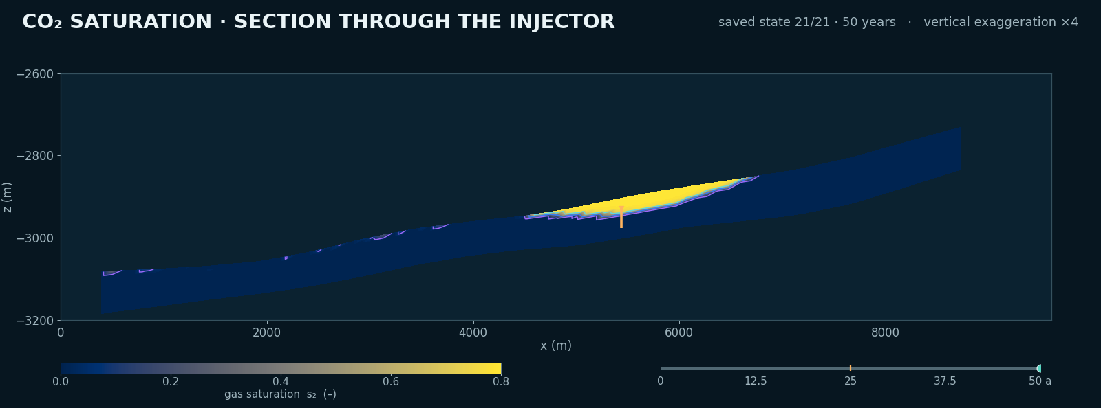
Year-50 vertical section through the injector with gas saturation on a fixed scale

Injector section

Fifty years through the formation

The plume rises to the formation roof, migrates up-dip during injection and holds its position after injection stops at year 25.

Section
y = 3300 m
Record
21 solver states
Saturation scale
Fixed 0–0.8
Geometry
Vertical exaggeration ×4
Method

The section is cut through the native tetrahedra at y = 3300 m. One frame is shown for each recorded solver state, with no temporal interpolation.
Open full evidence (new tab)

Three coordinated evidence views

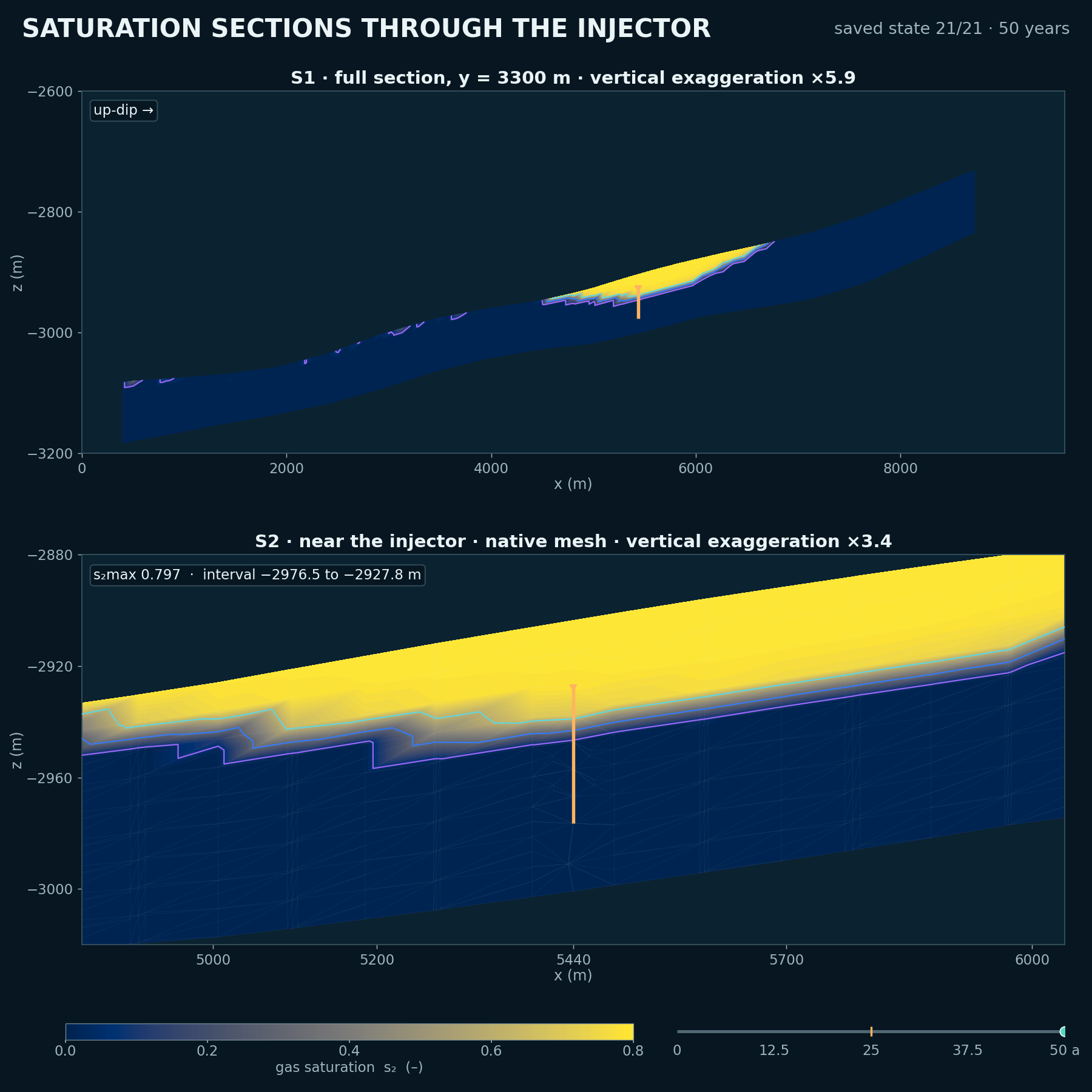
Year-50 vertical saturation sections through the injector, with the plume held beneath the formation roof

C-01

Vertical sections through the injector

The plume rises to the formation roof and stays held beneath it in both the formation-scale and near-injector views.

Record
21 solver states
Scale
Fixed gas saturation
Geometry
Vertical exaggeration ×3.4
Method

Two vertical cuts through the injector use the same fixed saturation scale: a formation-scale view and near-injector detail on the native mesh. One frame is shown for each recorded solver state, with no temporal interpolation.
Open full evidence (new tab)
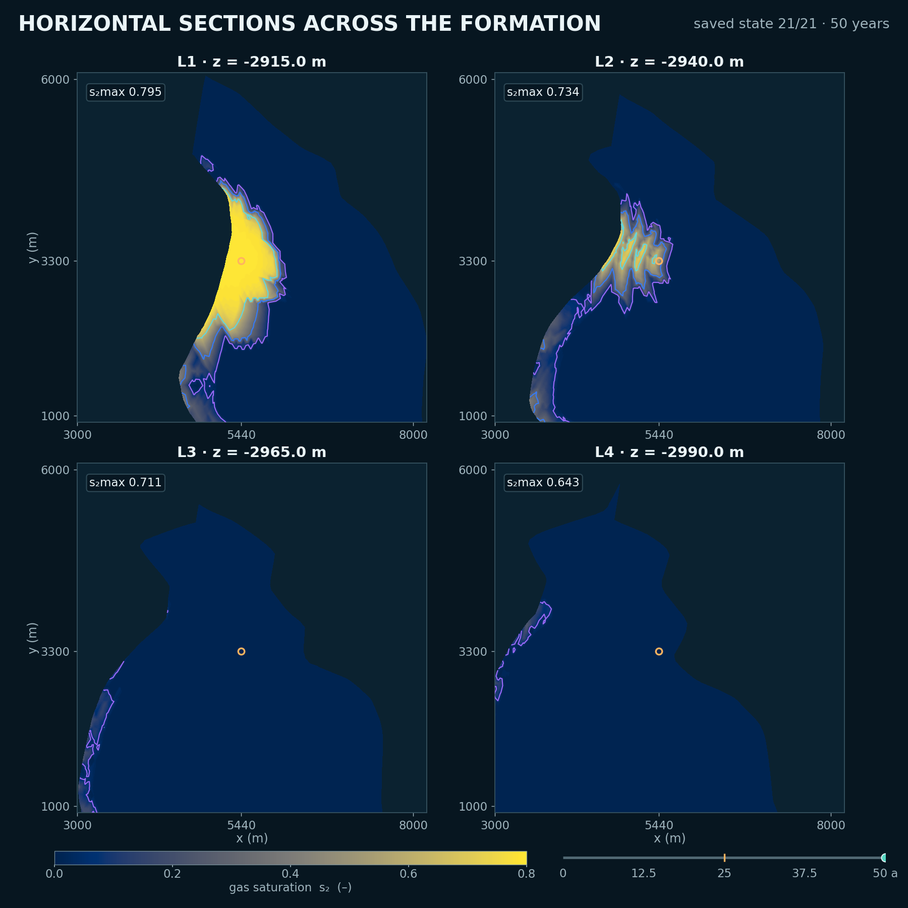
Year-50 plan-view sections at four depths, showing gas concentrated at the shallowest level

C-02

Horizontal sections across the formation

Gas collects beneath the formation roof across the four exact plan cuts, leaving the deepest level nearly empty.

Record
21 solver states
Sections
4 exact depths
Scale
Fixed gas saturation
Method

The cuts are at z = −2915, −2940, −2965 and −2990 m on the same fixed saturation scale. One frame is shown for each recorded solver state, with no temporal interpolation.

Open full evidence (new tab)
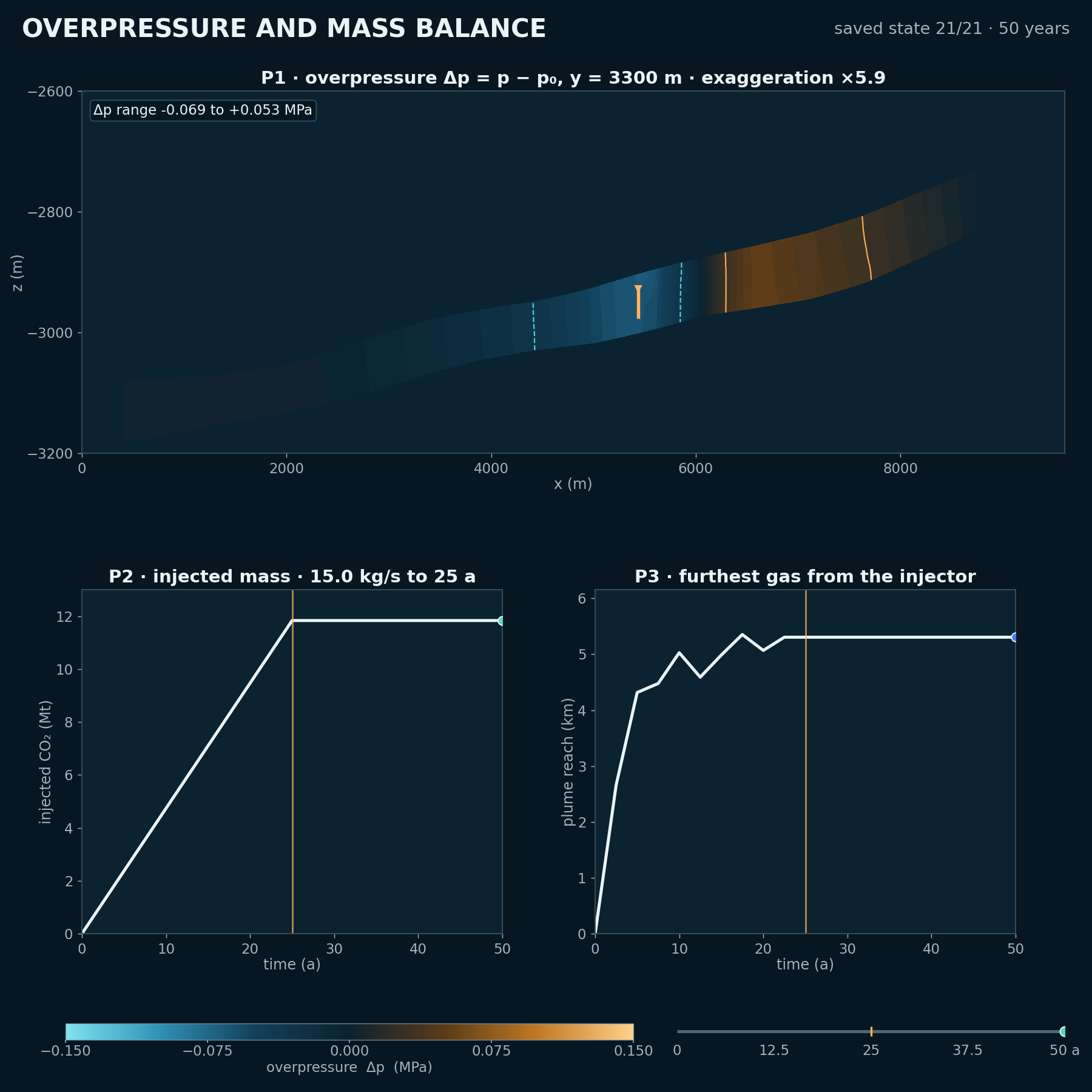
Year-50 overpressure section with injected-mass and plume-reach time series

C-03

Overpressure and mass balance

Injection reaches 11.8 Mt at year 25; after shut-in, the computed plume edge stabilises at 5.3 km.

Injection
15.0 kg/s to year 25
Total mass
11.8 Mt
Plume reach
5.3 km
Pressure scale
Fixed ±0.15 MPa
Method

Overpressure is Δp = p − p₀ on a fixed ±0.15 MPa scale. The adjacent plots report injected mass and plume reach against time across the 21 recorded solver states, with no temporal interpolation.

Open full evidence (new tab)
Evidence boundary

This page presents a recorded two-phase CO2-brine case in a Johansen-type formation: a 1-D injector coupled directly to the 3-D formation. It is not field validation, and it does not demonstrate production-well modelling or a separate meshing claim.

Bring a case

Have a geological storage decision to examine?

Tell us which injector, formation response or containment evidence your current assessment needs to resolve.

Discuss a storage case